![]()
Newton's and Fresnel's Diffraction Experiments
The Continuation of Newton's Diffraction
Experiments
Diffraction of Light at Slit and Hindrance
Interference-Angle Condition, Diffraction and
Imagery
Diffraction One After Another and with
Intermediate Imagery
Diminishing of Frequency of Light after
Diffraction
Inner and Outer Diffraction-Fringes at
Circular Openings
Superposition of Interference and Diffraction
Diffraction Experiments with Inhomogeneous
Illumination
Experiments with Polarized Light at Slit and
Double-Slit
The Background of Diffraction-Figures
Trial for Interpretation of Newton's Diffraction
Experiments
Consequences for Photons out of Newton's
Diffraction Experiments
Consequences for Structure of Electrons out of
that of Photons
The Thermally Conditioned Electromagnetic Field
Diffraction and Light-Emission of Electrons
Energy-Steps of Electrons in Magnetic Eigen-Field
Faraday's Electro-tonic States
Near-Field Optics with Regard to Newton's
Diffraction-Experiments
Consideration of Magnetic Moment of Electron
in Quantum Theories

Newton's and Fresnel's Diffraction Experiments
Photos of diffraction figures of triangular slit and Grimaldi's luminous edge confirm Newton's observations. Newton described the transition from inner to outer fringes of triangular slit and showed that bent light (Grimaldi's luminous edge) only comes out of narrow surroundings of every edge and not of the whole slit. On the contrary Fresnel communicated only easily calculable borderline cases and disregarded transitions of inner to outer fringes and localization of bent light. Since 1850 textbook authors took over Fresnel's theory and intercepted Newton's diffraction experiments.
Experiments and Figures
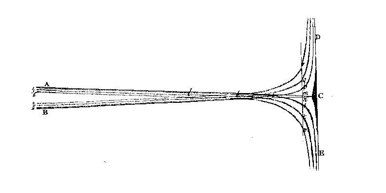
Figure. 1. Newton's drawing of diffraction at the triangular slit. Newton [1] III 10th observation. Newton used sunlight and a narrow hole in a shutter, distance to triangular slit 10 feet, and drawing plane 9 feet. With sunlight there are to observe only three (coloured) diffraction fringes but corresponding more with monochromatic light. ABC projection at triangular slit (shadow-limit).
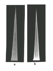
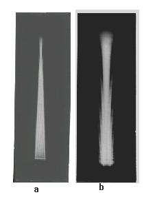
Figure 2. The diffraction figure of a triangular-slit with divergent light. A super-pressure mercury lamp with green filter was imaged by a condensor on a pinhole-diaphragm Ø 0.1 mm. In 1 m distance stood the triangular-slit 0... 3 mm. Exposure was fit to inner fringes.
a: A photoplate caught up the diffraction figure in a distance of 0.5 m from the slit. Supplementary two fold enlarged.
b: A photoplate in a distance of 2 m from the slit in original size.
Figure 3. The diffraction figure of a triangular slit with parallel light. The same arrangement as in figure 2 but before the triangular-slit stood a lens f' = 1 m, a and b are supplementary two folds enlarged.
a: Diffraction figure in 0.5 m distance,
b: Diffraction figure in 2 m distance.
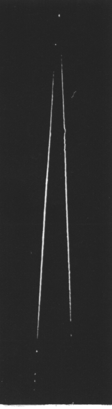 Figure 4. The luminous edge at the triangular slit. A super-pressure mercury lamp with a green filter illuminated with a condenser a 0.1 mm pinhole-diaphragm. In a distance of 1 m stood the triangular-slit, a razor-blade slit with a basis of 3 mm A plate camera with double extension and tessar 1 : 4,5, f' = 135 mm was focused at the triangular slit and set so far sideways that the direct light fell beside the lens.
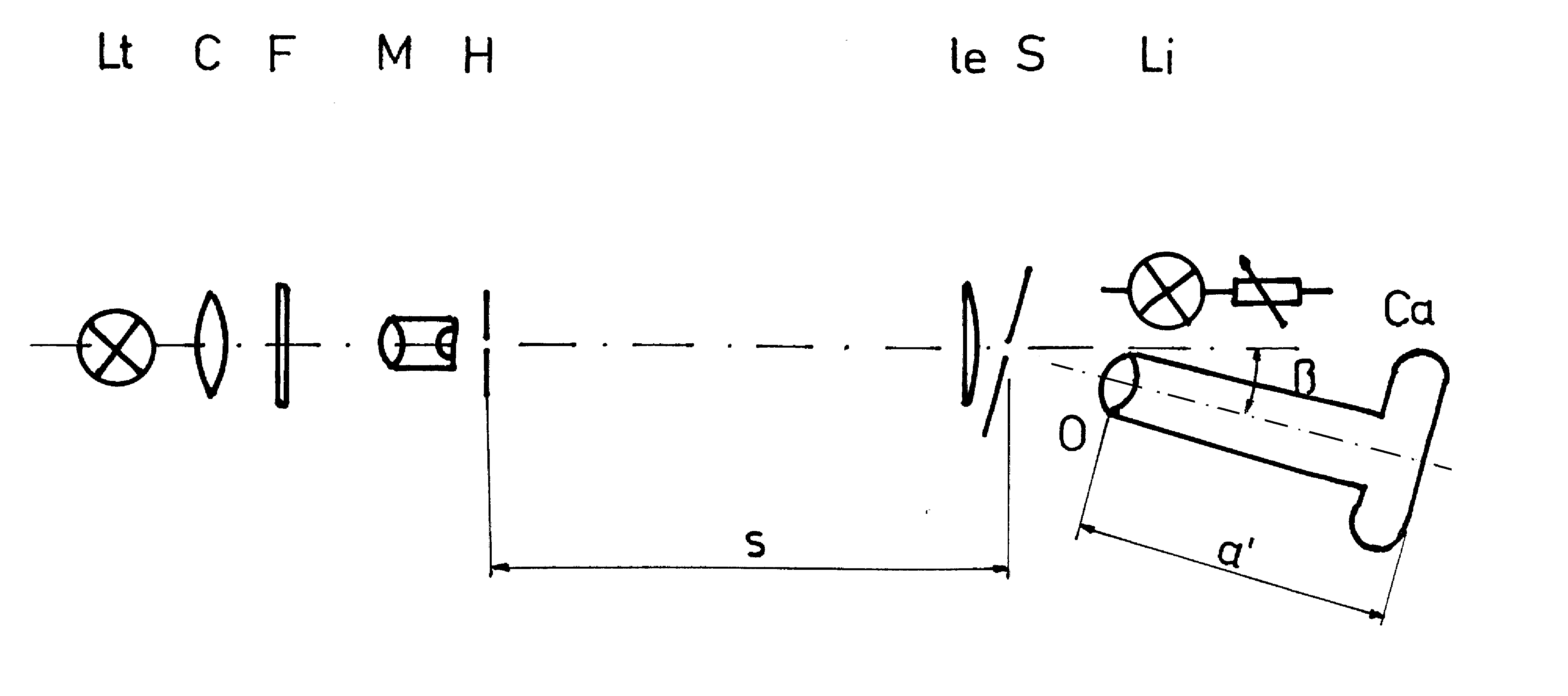
Figure. 5. Experimental arrangement for photography of luminous edge in macro-scale. Lt - light source for transmitted light, a super-pressure mercury lamp HBO 100; C - condenser; F - green filter; M -microscope-objective; H - pinhole diaphragm; Le - lens for parallel illumination; S - slit with 0.4 mm slit width consisting of 0.03 mm copper foil; S - distance from H to S; Li - light-source for incident light, a filament lamp operated with a adjustable transformer; O -photo lens; Ca - single lens reflex miniature camera with extension tubes; a' - image distance so that the same scale-ratio. In figures the upper edge of S is named light-side and the below edge shadow-side.
light-side shadow-side light-side shadow-side
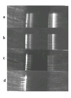
Figure 6. Photographic pictures of a slit according the arrangement of figure 5, O - tessar 1:2.8, f' 50 mm. The upper parts show the slit only with incident light, the lower parts additional with transmitted light illumination.a. Ø H = 50 mm, s = 1 m, f' = 50 mm, b = 7°,
b. Ø H = 50 mm, s = 0,5 m, f' = 50 mm, b = 7°,
c. Ø H = 50 mm, s= 1 m, f' = 50 mm, b = 15°,
d. Ø H = 50 mm, s = 1 m, f' = 50 mm, b = 30°.
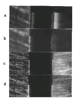
Figure 7. As figure 6. O - tessar 1:4.5, f' = 135 mm or microtar f' = 10 mm.
a. Ø H = 50 mm, s = 1 m, f' = 135 mm, b = 7°,
b. Ø H = 50 mm, s = 1 m, f' = 135 mm, b = 14°,
c. Ø H = 50 mm, s = 1 m, f'= 10 mm, b = 7°,
d. Ø H= 50 mm, s = 1 m, f' = 10 mm, b = 14°.
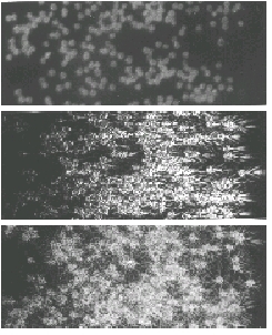
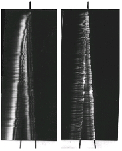
Figure 8. Photos of the scattering figures of spores of ground pine (lycopodium) according to figure 5 but instead of Lt up to H a helium-neon laser HNA 188 and instead of the slit S a glass-disk with the spores of ground pine in the same scale ratio as figure 6.
a: Only incident light,
b: Only transmitted light, b = 7°,
Figure 9. Photos of the top of a triangular-slit according figure 5 in the same scale as figure 6. í Ø B = 0.5 mm, s = 1 m. The outside lines point to the position of the slit.
a: b = 7°,
b: b = 15°
.
Consequences
Fresnel [2] confirmed in his first paper about diffraction that bent light comes only 'from the edge', but with it he could not calculate the inner diffraction-fringes of hindrance (and the outer of slit). Also he established that it is not permitted to mask within the slit simple the sphere between the spheres of which bent light is coming. If one do so, the diffraction figure of double-slit will arise. Therefore in his second paper Fresnel took as pretend Huygens' principle and gave no more mention or respect to physical contradiction in origin of bent light; the mathematical description in large distances was satisfied to him, and later he drew his waves as circles not up to the hindrance. Fresnel was conscious of the weaknesses of his theory. From about 1850 the textbook authors left out Newton's diffraction experiments and so they could feigned a simple but misleading description. That the sphere between bent light is coming should not be masked,
Therefore it is not necessary that everyone have to test experimentally the communications of Fresnel [2] over his measurements; it is sufficient to examine the extrapolation of formula (1) as inadmissible and wrong by comparison with Newton's diffraction experiments.
Here Rubinowicz [11] attempted to bridge over this contradiction. In the function theory it is possible to transform a line integral into a plane-integral. With light, exhibited by an e-function as analytic function, he believed to have removed that contradiction; according to this it is indifferent if bent light is coming from the edge or from the plane. However, light is no analytic function and bent light is coming neither from the edge nor from the whole plane but out of narrow surroundings of every edge. The light-line of Grimaldi is not to exhibit as a line-integral. That bent light is coming only out of the surroundings of edges is a well-known fact since centuries, never one has shown that bent light comes from the whole slit-plane, but nevertheless general plane-integrals were used for calculation of diffraction. has to be establish in future papers, but it does not justify the extrapolation.
It is to sumarize that Fresnel in later papers
- Could calculate the diffraction-figure of half-plane, they have characteristic unequal intervals of diffraction-fringes, by Fouriertheorem with the Fresnel-integral, Huygens' principle, and Young's interference-principle.
- Could calculate diffraction at hindrance with inner and at slit with outer diffraction-fringes, at, which have characteristic constant intervals of diffraction-fringes, by Fourier-theorem with goniometric function {formula (1)}. Especially point 2nd is valid only in very large distances.
- By Newton bent light is coming out of a small surroundings of edge and falsely by Young and Fresnel only from the edge.
- The diffraction at triangular-slit demonstrates that in short distances and great slit-width arise the inner diffraction-fringes of slit (resp. outer of hindrance), which correspond to the diffraction figure of half-plane with the edges as half-plane. First in larger distances arise the outer diffraction-fringes of slit (resp. the inner of hindrance) which stated in text-books after 1850 as only diffraction-figure of slit. First here the inadmissible and wrong extrapolation is shown evidently.
![]()
© 2006 by tediamedia • info@gebeugtes-licht.de