![]()
Newton's and Fresnel's Diffraction Experiments
The Continuation of Newton's Diffraction
Experiments
Diffraction of Light at Slit and Hindrance
Interference-Angle Condition, Diffraction and
Imagery
Diffraction One After Another and with
Intermediate Imagery
Diminishing of Frequency of Light after
Diffraction
Inner and Outer Diffraction-Fringes at
Circular Openings
Superposition of Interference and Diffraction
Diffraction Experiments with Inhomogeneous
Illumination
Experiments with Polarized Light at Slit and
Double-Slit
The Background of Diffraction-Figures
Trial for Interpretation of Newton's Diffraction
Experiments
Consequences for Photons out of Newton's
Diffraction Experiments
Consequences for Structure of Electrons out of
that of Photons
The Thermally Conditioned Electromagnetic Field
Diffraction and Light-Emission of Electrons
Energy-Steps of Electrons in Magnetic Eigen-Field
Faraday's Electro-tonic States
Near-Field Optics with Regard to Newton's
Diffraction-Experiments
Consideration of Magnetic Moment of Electron
in Quantum Theories

Diffraction of Light at Slit and Hindrance
As introduction is described that the diffraction figure of the halfplane is building up~ and first in a distance of 105 l appears (by parallel incident light) the accustomed figure. Slit and hindrance of same dimensions have as images in a schlieren apparatus by Abbe on both sides of every edge-image a double-stripe (breadth <0.1 mm) with a small dark space. That means that bent light seems to come out of analogous spheres. Without schlieren apparatus originate edge symmetrical exchanged (equal only in special cases) equal diffraction figures with inner and outer diffraction fringes. General remarks about inner and outer diffraction fringes complete this paper.
Experiments and their results
Figure 1. Experimental arrangement for taking photos of the diffraction-figures of half-plane in short distances with parallel incident light. L - light-source, a super-pressure mercury-lamp HBO 100; C - condenser; F - green-filter: M - microscope-objective; D - pinhole-diaphragm, a spinning nozzle 50 mm; Le - lens f' = 1 m; s = 1 m; s' - distance H - P; H - half-plane; P - photofilm.
Figure 2. Photometer-curves of diffraction-figures of half-plane in dependence of the distance s' according to figure 1. In the ordinate the photometer-curves are so displaced that every curve comes about to the place that corresponds with the root of the distance s¢ . The marked numbers mean the distance s' in mm; E - film close behind the edge.


a: wire image 2 mm before the cross-plane,
b: wire image in the cross-plane,
c: slit image in the cross-plane,
d: slit image 2 mm before the cross-plane.
Figure 3 (left). Images of hindrance and slit in a schlieren-apparatus after Abbe in Nieke [5] figure 1. Wire and slit 0.5 mm. a' : a - 4 and optical enlarged.
Figure 4. Image of hindrance and slit of the measurement 0.2 mm in a schlieren-apparatus. a ... d as figure 3..
Figure 5 (right). Image of hindrance and slit of the measurement 0.1 mm in a schlieren-apparatus. a ... d as figure 3.
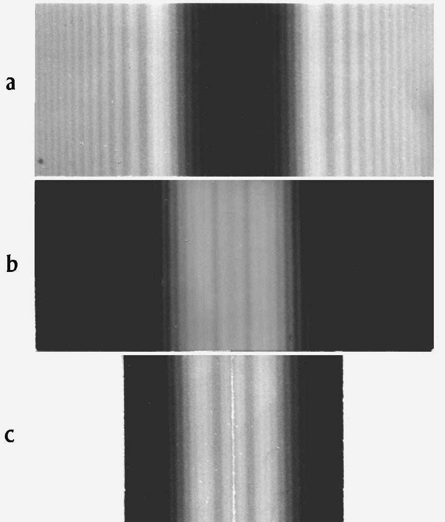
Figure 6. Diffraction-figures of hindrance and slit in 0.1 m distance without schlieren-apparatus in Fresnel's manner of observation and in parallel incident light. a: wire f 1.5 mm b: slit 1.5 mm. c: the photo a is cut in the middle to pieces and edge-symmetrical pasted
Figure 7. Diffraction-figure of the same hindrance and slit as figure 6 but in 0.3 m distance. a ... c as in figure 6.
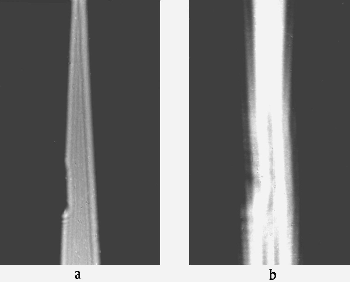
Figure 8. Diffraction-figures at a triangular-slit with a chip. A super-pressure mercury-lamp with a green filter was projected on a pinhole-diaphragm 0.05 mm. In 1 m distance stood a triangular-slit 0.. .3 mm with a copper-foil chip at one edge. That is in divergent light. a: diffraction-figure in 0.1 mm distance, b: diffraction-figure in 0.5 mm distance.
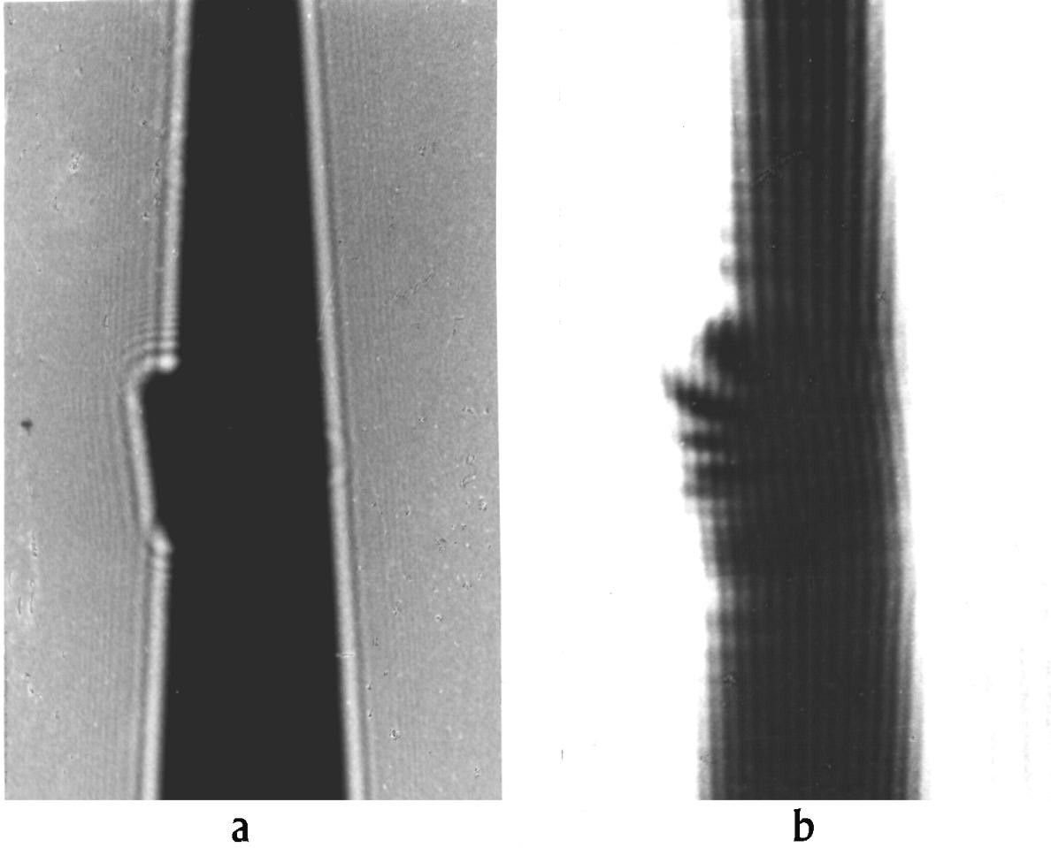
Figure 9. Diffraction at a triangular-hindrance with a chip. Illuminated as described in figure 8 but in 1 m distance of the pinhole-diaphragm stood a triangular-hindrance 0 ... 3 mm with a chip on one edge. a: diffraction-figures in 0.1 m distance, b: diffraction-figures in 0.5 m distance.
Discussion
As deficiency in description of diffraction at complementary screens is to find that consciously or unconsciously was avoided a discussion about inner and outer diffraction-fringes. That happened because the transition from inner to outer fringes of slit are not to explain hitherto.
Here Nieke [10] directed that the statement: "Suffice separated edges have to give the diffraction-figure of the half-plane", is not valid but it is to explain why at the same slit-width in short distances results inner and in large distances outer fringes.
Only with Fraunhofer's manner of observation this difficulty was removed for there appear (in the focus-plane) only outer diffraction-fringes. In a real description of Babinet's theorem eyes dare not shut against difficulty. In return for it yields a clear notion of Babinet's theorem if is accented the edge-symmetric exchange of diffraction-appearances. Then only in special-cases one finds agreement if the central-figure is took out.
Experiments with chips at edges show that one can experiment in the slit even if Born a. Biem [14] denied this, but it is to distinguish between inner and outer fringes. At inner fringes of slit and outer fringes of hindrance the chip effects only to the diffraction-figure of that edge on which it is fixed. In larger distances if appear outer fringes of the slit and inner fringes of hindrance then the chip effects on the whole diffraction-figure of these fringes.
Lohmann a. Sinzinger [15] examined Babinet's principle if only a part of a computer-holography was complementary exchanged. They termed this case as local Babinet-effect. The principle of edge-symmetric exchange can not be effective because they compare only with Fraunhofer's manner of observation.
References
[1] A. J. Fresnel, Ouvre Complétes, Paris 1866; Abhandlungen über die Beugung des Lichtes. Ostwalds Klassiker Nr. 215, Engelmann, Leipzig 1926.
[2] H. Boersch, Naturwiss. 28 (1940) 711.
[3] J .Hiller a. E. Ramberg, J. Appl. Phys. 18 (1947) 48
[4] I. Newton, Opticks, or a Treatise of the Reflexions, Refractions, Inflections and Colours of Light. London 1704; Opera quac exstant omnis, Tom IV. London 1782; Optics, reprint, Bruxelles 1966; Optik II + III, Übers. W. Abendroth, Ostwald's Klassiker Nr. 97, Engelmann, Leipzig 1898; Neuauflage: Bd. 96/97, Vieweg, Braunschweig 1983; Optique, Trad. J. P. Marat, Paris 1787; Bourgois 1989.
[5] H. Nieke, Newton's Diffraction Experiments and their Continuation. Halle 1997. Paper 2.
[6] A. Babinet, C. R. 4 (1837) 638.
[7] J. v. Fraunhofer, Gesammelte Schriften. Verl. bayr. Akad. Munchen 1888.
[8] L. Bergmann u. Cl. Schaefer, Lehrbuch der Experimentalphysik. Bd. III, T 1. Gruyter, Berlin 1956, S. 276.
[9] R. W. Pohl, Einführung in die Optik. Springer, Berlin, Gbttingen, Heidelberg 1948, S. 87.
[10] As [5], paper 1.
[11] M. V. Laue, In: Handb. Experimentalphysik XVIII, Leipzig 1928, S. 307.
[12] A. W. Maue, Z. Naturforschung 4 a (1949) 393.
[13] C. Malgange u. J. Gronkowski, phys. stat. sol. (a) 85 (1984) 389.
[14] M. Born u. W. Biem, Phys. Bl. 25 (1969) 110.
[15] A. W. Lohmann a. S. Sinzinger, J. Opt. Soc. Am. A 9 (1992) 1154.
![]()
© 2006 by tediamedia • info@gebeugtes-licht.de